Reinforcement calculation of oblique section of flexural member
10.3.1 When fiber composite material strips (hereinafter referred to as strips) are used to strengthen the shear bearing capacity of the oblique section of the flexural member, it shall be pasted into a ring hoop or other effective U-shaped hoop perpendicular to the axial direction of the member (Fig. 10.3.1); oblique pasting is not allowed.
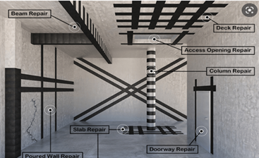
Figure 10.3.1 Fiber composite material shear hoop and its pasting method
1—glue anchor; 2—steel plate layer; 3—fiber fabric layer; 4—plate; 5—anchor plus glue anchor; 6—U-shaped hoop; 7—beam
10.3.2 The oblique section of the flexural member after reinforcement shall meet the following requirements:
When hw/b≤4
![]()
When hw/b≥6
![]()
When 4<hw/b<6, it is determined by linear interpolation.
In the formula: V——the design value of shear force after strengthening the oblique section of the member (kN);
βc—influence coefficient of concrete strength, adopted according to the current national standard "Code for Design of Concrete Structures" GB 50010;
ƒc0——Design value of concrete axial compressive strength of original member (N/mm²);
b——width of rectangular section, web width of T-shaped or I-shaped section (mm);
h0——section effective height (mm);
hw——web height of section (mm), for rectangular section, take the effective height; for T-shaped section, take the effective height minus the flange height; for I-shaped section, take the clear web height.
10.3.3 When adopting circular (closed) hoops or U-shaped hoops composed of strips for shear reinforcement of reinforced concrete beams, the bearing capacity of the inclined section shall be determined according to the following formula:
![]()
In the formula: Vb0——the oblique section bearing capacity of the beam before strengthening (kN), which should be calculated according to the current national standard "Code for Design of Concrete Structures" GB 50010;
Vbf——the increase value of the bearing capacity of the oblique section of the beam after the tape is strengthened (kN);
ψvb——reduction coefficient of shear strength related to strip anchoring mode and stress conditions (Table 10.3.3);
ƒf——The design value of the tensile strength of the fiber composite material used for shear reinforcement (N/mm²), which shall be in accordance with Table 4.3.4-1, Table 4.3.4-2 and Table 4.3.4-3 respectively according to the type of fiber composite material The specified tensile strength design value is multiplied by the adjustment factor 0.56 to determine; when it is a frame beam or a cantilevered member, the adjustment factor is changed to 0.28;
Af——The entire cross-sectional area of the fiber composite strips configured at the same section to form a ring or U-shaped hoop (mm²), Af=2nfbftf, nf is the number of layers pasted by the strip, bf and tf are the strip width and Strip monolayer thickness;
hf——the vertical height of the strip pasted on the side of the beam (mm); for the ring hoop, take hf=h;
sf - spacing of fiber composite strips (Fig. 10.3.1b) (mm).
Table 10.3.3 Shear strength reduction coefficient ψvb value
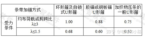
Note: When λ is an intermediate value, determine the value of ψvb by linear interpolation.
10.4 Reinforcement Calculation of Normal Sections of Compression Members
10.4.1 Axial compression members can be reinforced by continuously pasting fiber fabrics in the circumferential direction without intervals along their entire length (referred to as the circumferential confinement method).
10.4.2 The use of the circumferential confinement method to strengthen axial compression members is only applicable to the following situations:
1 Circular section column with slenderness ratio l/d≤12;
2 Square or rectangular cross-section columns with slenderness ratio l/d≤14, section height-to-width ratio h/b≤1.5, section height h≤600mm, and rounded corners.
10.4.3 For the axial compression member with circumferential enclosure, the bearing capacity of its normal section shall comply with the following formula:
In the formula: N—design value of axial pressure after reinforcement (kN);
ƒc0——Design value of concrete axial compressive strength of original member (N/mm²);
σl——effective restraint stress (N/mm²);
Acor—concrete area in the circumferential enclosure (mm²); circular section:
![]()
D——diameter of circular cross-section column (mm);
b——square section side length or rectangular section width (mm);
h—height of rectangular section (mm);
r——the rounding radius of the corners of the section (chamfering radius);
βc—influence coefficient of concrete strength; when the concrete strength grade is not greater than C50, βc=1.0; when the concrete strength grade is C80, βc=0.8; it is determined by linear interpolation;
kc—the effective confinement coefficient of the circumferential enclosure, adopted in accordance with the provisions of Article 10.4.4 of this code;
ρf—circumferential enclosure volume ratio, calculated according to the provisions of Article 10.4.4 of this code;
Ef——Elastic modulus of fiber composite material (N/mm²);
εfe——design value of effective tensile strain of fiber composite material; εfe=0.0035 for important components; εfe=0.0045 for general components.
10.4.4 The calculation parameters kc and ρf of the circumferential enclosure shall be determined according to the following provisions:
1 Determination of effective constraint coefficient kc value:
1) Circular section column: kc=0.95;
2) Square and rectangular cross-section columns shall be calculated according to the following formula:
![]()
In the formula: ρs—the reinforcement ratio of the longitudinal reinforcement in the column.
 English
 العربية
 Español
 Русский