About us | Email: info@wolf-fix.com
Languages

Find Wolfix, find your requested new materials

Structural regulations
When the positive moment zone of the reinforced concrete flexural member is reinforced with a positive section, the fiber composite material pasted axially on the tensile surface shall extend to the edge of the support, and shall be at the end of the fiber composite material (including the truncation point). ) and both sides of the point where the concentrated load acts, the U-shaped hoop (for the beam) or the transverse layer (for the plate) of the fiber composite material is set.
10.9.2 When the fiber composite extends to the edge of the support and still does not meet the extension length specified in Article 10.2.5 of this code, the following anchoring measures shall be taken:
1 For a pair of beams, no less than three U-shaped hoop anchors shall be evenly arranged within the extended length range (Fig. 10.9.2a), and one of them shall be arranged at the end of the extended length. The U-shaped hoop is made of fiber composite material; the sticking height of the U-shaped hoop should be the cross-sectional height of the beam; when the beam has a flange or a cast-in-place floor slab, it should extend to its bottom surface. The width of the U-shaped hoop should not be less than 2/3 of the width of the reinforced fiber composite for the end hoop, and should not be less than 150mm; 100mm. The thickness of the U-shaped hoop should not be less than 1/2 of the thickness of the fiber composite material reinforced by bending.
2 For the plates, beadings perpendicular to the direction of the stressed fibers shall be arranged throughout the extended length (Fig. 10.9.2b). The bead is made of fiber composite material. In addition to arranging one bead at the end of the extension length, it is advisable to arrange 1 to 2 layers evenly within the extension length. The width of the bead should not be less than 3/5 of the strip width of the flexurally reinforced fiber composite material, and the thickness of the bead should not be less than 1/2 of the thickness of the flexurally reinforced fiber composite material.
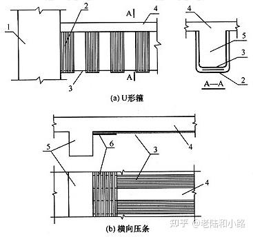
Figure 10.9.2 Anchorage measures at the ends of beams and slabs pasted with fiber composites
1—column; 2—U-shaped hoop; 3—fiber composite material; 4—plate; 5—beam; 6—transverse layer
Note: (a) The bead is not drawn in the figure.
3 When the fiber composite material extends to the edge of the support, the end hoop (or end bead) should be changed to a mechanical anchoring measure made of steel and reliable force transmission in the following situations:
1) The extendable length is less than half of the length calculated according to formula (10.2.5);
2) The fiber composite material used for reinforcement is a preformed plate.
10.9.3 When fiber composite materials are used to strengthen the positive section bearing capacity of the negative moment zone of the flexural member, the following construction measures shall be taken:
1 When there is no obstacle at the support, the fiber composite material should be pasted continuously within the range of the negative bending moment envelope; the truncation point of its extension length should be located in the positive bending moment area, and the distance from the positive and negative bending moment conversion point should not be less than 1m.
2 Although there is an obstacle at the support, but there is a cast-in-place slab on the beam and it is allowed to bypass the column position, it is advisable to paste the fiber composite material on the slab surface within the range of 4 times the slab thickness (hb) on the beam side (Figure 10.9 .3-1).
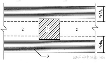
Figure 10.9.3-1 Bonding fiber composites bypassing the post
1—column; 2—beam; 3—fiber composite material pasted on the top surface of the board; hb—board thickness
3 At the end nodes of beams and columns on the top floor of the frame, when the fiber composite material can only be attached to the edge of the column and cannot be extended, structural adhesive should be used to attach L-shaped carbon fiber plate or L-shaped steel plate for bonding and anchoring (Figure 10.9.3- 2). The total cross-sectional area of the L-shaped steel plate shall be calculated according to the following formula:
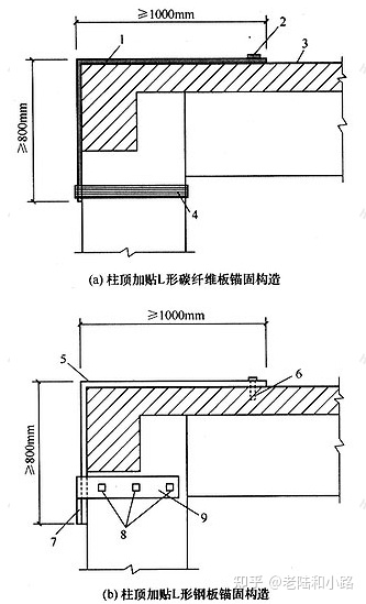
Figure 10.9.3-2 L-shaped carbon fiber plate or steel plate anchoring structure attached to the top of the column
1—Paste L-shaped carbon fiber plate; 2—Lateral bead; 3—Fiber composite material; 4—Fiber composite material enclosure; 5—Paste L-shaped steel plate; 6—M12 anchor bolt; 7—Add welded roof (pre-welded); 8—6.8 grade anchor bolt with d≥M16; 9—U-shaped steel hoop plate glued to the column
In the formula: Aa,1—the cross-sectional area of the L-shaped steel plate to be pasted at the support;
ψf——strength utilization factor of fiber composite material, adopted according to Article 10.2.3 of this code;
ƒf——design value of tensile strength of fiber composite material, adopted according to Article 4.3.4 of this code;
Af—the cross-sectional area of the fiber composite material actually pasted at the support;
ƒy—design value of tensile strength of L-shaped steel plate.
The total width of the L-shaped steel plate should not be less than 0.9 times the beam width, and should be composed of multiple L-shaped steel plates.
4 When there is no cast-in-place slab on the beam, or when strengthening anchorage measures are required at the support of the negative bending moment area, the construction method of gluing L-shaped steel plates (Fig. 10.9.3-3) can be adopted. However, the grade, diameter and quantity of the anchor bolts of the hoop plate in the column shall be determined by calculation. When there is a cast-in-place slab on the beam, this structure can also be used for anchoring. The U-shaped steel hoop plate passes through the floor. The half-stack drilling method should be used to drill a flat hole on the slab to insert the hoop plate, and then Seal with structural glue.
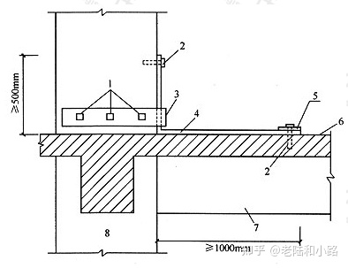
Figure 10.9.3-3 Example of anchorage structure with L-shaped steel plate and U-shaped steel hoop plate attached to the middle of the column
1—6.8 grade anchor bolt with d≥M22; 2—M12 anchor bolt; 3—U-shaped steel hoop plate, glued to the column; 4—glued L-shaped steel plate;
5—horizontal steel bead, anchored on the floor; 6—reinforced fiber composite material; 7—beam; 8—column
10.9.4 When the flexural members to be reinforced are plates, shells, walls and cylinders, the fiber composite material shall be pasted in multiple densely distributed ways, and the width of each strip shall not be greater than 200mm; uncut strips shall not be used The entire fabric is covered with stickers.
10.9.5 When the multi-layer fiber fabric pasted by the bending member is allowed to be cut off, the adjacent two layers of fiber fabric should be cut off layer by layer according to the principle of short inside and long outside; And a U-shaped hoop should be added at the truncation point.
10.9.6 When fiber composite materials are used to reinforce the oblique section bearing capacity of reinforced concrete beams or columns, the structure shall meet the following requirements:
1 Ring hoops or self-locking U-shaped hoops at the ends should be selected; when hoops are only provided according to structural needs, general U-shaped hoops can also be used;
2 The fiber bearing direction of the U-shaped hoop should be perpendicular to the axial direction of the member;
3 When fiber composite strips are used for ring hoops, end self-locking U-shaped hoops or general U-shaped hoops, the net spacing sf,n (Figure 10.9.6) shall not be greater than the current national standard "Code for Design of Concrete Structures" 0.70 times the maximum stirrup spacing specified in GB 50010, and should not be greater than 0.25 times the beam height;
4 The sticking height of the U-shaped hoop shall comply with the provisions of Article 10.9.2 of this code; if there is no self-locking device at the upper end of the U-shaped hoop, the longitudinal bead shall be pasted for anchoring;
5 When the height h of the beam is greater than or equal to 600mm, a longitudinal waist pressure belt should be added at the waist of the beam (Figure 10.9.6); if necessary, a self-locking device can also be added at the end of the waist pressure belt.
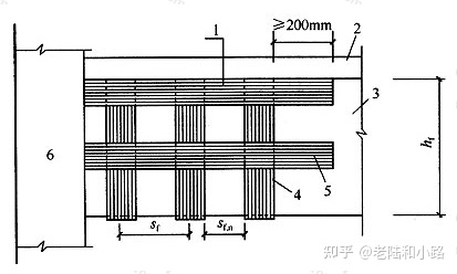
Figure 10.9.6 Longitudinal waist compression belt
1—longitudinal bead; 2—board; 3—beam; 4—U-shaped hoop; 5—longitudinal waist bead;
6—column; sf—central spacing of U-shaped hoops; sf,n—clear spacing of U-shaped hoops; hf—vertical height of strip pasted on the side of the beam
10.9.7 When the reinforced concrete column is reinforced by the circumferential enclosure of the fiber composite material or the seismic reinforcement to improve the ductility, its structure shall meet the following requirements:
1 The number of layers of fiber fabrics bounding in the circumferential direction shall not be less than 2 layers for circular cross-section columns; it shall not be less than 3 layers for square and rectangular cross-section columns; For rectangular cross-section columns, the minimum number of layers may also be 2 layers.
2. The lap width between the upper and lower layers of the hoop enclosure shall not be less than 50mm, and the extension length of the hoop cut-off point of the fiber fabric shall not be less than 200mm, and the lap joint positions of each strip shall be staggered from each other.
10.9.8 When the fiber composite material is pasted along the column axis to strengthen the bearing capacity of the normal section of the large eccentric compression column, the fiber composite material should avoid the floor beam and pass through the floor along the column angle, and the fiber composite material should be a plate; The anchor structure at the upper and lower ends shall be mechanically anchored. At the same time, efforts should be made to avoid cutting off the fiber composite at the floor.
10.9.9 When U-shaped hoops, L-shaped fiberboards or hoop enclosures are used for reinforcement and need to be bypassed at the external corners of the components, the corners of the cross-section shall be rounded by grinding before pasting (Figure 10.9.9). The rounding radius r of beams should not be less than 20mm for carbon fiber and glass fiber; it should not be less than 15mm for aramid fiber; the rounding radius of column should not be less than 25mm for carbon fiber and glass fiber; it should not be less than 20mm for aramid fiber .